
If you’ve ever flashed firmware over USB, you’ve already lived in the future. Convenient, fast, and just a little
bit boring (in the same way microwaves are boring because they work).
But rewind the tape to an era when “IDE” meant “I Draw Everything” and debugging involved eyeballing LEDs like a
detective in a noir film. That’s where the trainer board comes in: switches, lights, and hands-on control
designed to teach you how a chip thinksone blink at a time. A modern retro-style trainer built around Motorola’s
delightfully oddball 1-bit processor brings that vibe back, without requiring you to own a time machine.
In this deep dive, we’ll unpack what Motorola’s 1-bit “Industrial Control Unit” (ICU) actually is, why it existed,
and why a retro-style trainer like the PLC14500 Nano is such a smart way to learn low-level logic, control systems,
and the roots of programmable automation. Along the way, we’ll translate the chip’s minimalist instruction set into
practical, real-world examplesbecause “1-bit CPU” sounds like a joke until you realize it can still run the show.
Meet Motorola’s 1-Bit “CPU” (Yes, One Bit)
The Motorola MC14500 (and its common variant, the MC14500B) was designed for simple control tasks in the late 1970s,
and it’s exactly what it sounds like: a CMOS processor that operates on a 1-bit data word. That doesn’t mean its
instructions are 1-bit (it uses a 4-bit opcode with 16 instructions). It means its core “thinking” happens one bit
at a timeperfect for decision-making based on on/off signals, relay logic, and straightforward automation.
Where a typical microprocessor tries to be a generalistarithmetic, registers, addressing modes, stacks, and so on
the MC14500 is more like a specialist tool. Its job is to chew through single-bit inputs, combine them with simple
boolean operations, and drive outputs. That’s why it shows up in discussions of ladder logic and programmable logic
controllers (PLCs): it was built to replace heaps of hardwired combinational logic with something programmable,
while staying simple enough to be understood (and repaired) by the humans on the factory floor.
Why a 1-Bit Chip Wasn’t a Bad Idea
In control applications, “data” often looks like switch open/closed, sensor triggered/not,
motor on/off, limit reached/not. That’s boolean logic territory. A 1-bit CPU lets you
build programmable sequencing and conditional behavior without wasting silicon on features you don’t need.
The MC14500 is also famously minimal in what it includes internally. A lot of what we expect inside a “processor”
(program counter, I/O selection, output latching, sometimes even subroutine support) is pushed out to external logic.
That sounds inconvenientuntil you realize it makes the architecture extremely teachable. You can literally see, and
design, the pieces around it.
How the MC14500 Thinks: A Tiny Architecture With Big Teaching Value
At the heart of the chip is a single result register (often called RR). Every operation basically
updates RR, and RR becomes the “state of the conversation” between your code and the outside world.
You load a bit, combine it with RR (AND/OR/XNOR), and optionally store RR out to an output or memory bit.
The Instruction Set: 16 Opcodes, Plenty of Personality
The MC14500’s entire instruction set fits in your headassuming your head has had coffee. Here’s a friendly view of
the classic 16-instruction lineup (mnemonics vary slightly by reference, but the core set is consistent):
| Opcode | Mnemonic | Plain-English Meaning |
|---|---|---|
| 0x0 | NOPO | No operation (flag behavior depends on implementation) |
| 0x1 | LD | Load DATA into RR |
| 0x2 | LDC | Load complemented DATA into RR |
| 0x3 | AND | RR AND DATA → RR |
| 0x4 | ANDC | RR AND (NOT DATA) → RR |
| 0x5 | OR | RR OR DATA → RR |
| 0x6 | ORC | RR OR (NOT DATA) → RR |
| 0x7 | XNOR | RR becomes 1 if RR equals DATA |
| 0x8 | STO | Store RR to DATA (write enabled) |
| 0x9 | STOC | Store complemented RR to DATA (write enabled) |
| 0xA | IEN | Input enable control via DATA |
| 0xB | OEN | Output enable control via DATA |
| 0xC | JMP | Signal a jump (external program counter logic required) |
| 0xD | RTN | Signal return (external subroutine logic required) |
| 0xE | SKZ | Skip next instruction if RR = 0 |
| 0xF | NOPF | No operation (flag behavior depends on implementation) |
The key takeaway: you’re not “computing” in the modern sense. You’re sequencing logicand that’s
exactly what control systems care about.
External Program Counter: The Chip Doesn’t Drive the Road, It Holds the Map
One of the MC14500’s most interesting design choices is what it leaves out. The chip does not include a built-in
program counter, so your system design supplies that function externally. This has two surprising benefits:
- Flexibility: memory size and addressing approach can be tailored to the job.
- Visibility: you can literally watch instruction flow and understand it at the signal level.
The downside is also the upside: if you want fancier control flow (jumps, returns, subroutines), you’re responsible
for wiring up the supporting logic. But for learning, that’s a gift. It forces you to understand what “jump” really
means electrically, not just conceptually.
So… What’s a Retro-Style Trainer Board, Exactly?
A “trainer” is the hands-on hardware equivalent of a workbook: the chip is on the board, and the board surrounds it
with the human-friendly controls needed to learn. Historically that meant toggle switches to enter values, buttons to
step the clock, and a forest of LEDs to display bus lines and internal states. Modern development boards hide all that
behind a nice abstraction layer. Trainers do the opposite: they proudly expose the guts.
The retro-style trainer approach is especially perfect for the MC14500 because the chip is fundamentally about
signals. When you can see those signalsand step through themconcepts like “instruction fetch,”
“state,” “write enable,” and “I/O mapping” stop being textbook words and start being something your brain can feel.
The PLC14500 Nano: Vintage Vibes, Modern Convenience
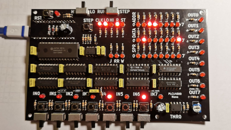
One well-known modern take is the PLC14500 Nano: a retro-style trainer designed to help people learn the MC14500, PLC
concepts, and ladder-logic thinking with a very “1970s front panel” attitude. It’s loaded with LEDs that reveal the
status of buses and registers, and it supports step-by-step execution so you can watch a program unfold one cycle at a
time. It’s basically a logic documentary, except you’re the director.
Trainer Features That Actually Matter (Not Just “Cool Blinky Lights”)
- Step-by-step execution: manual stepping turns the chip into a classroomeach clock tick is a lesson.
-
Multiple clock modes: fast for normal operation, slow for “watch it breathe,” and manual for deep
debugging. -
On-board I/O: multiple inputs (toggle/momentary) and outputs (LEDs) let you build real control demos
without extra wiring. -
Program memory on the board: enough space to build meaningful examples, while staying small enough to
stay understandable. -
Tooling that doesn’t ruin the illusion: a modern USB-friendly helper microcontroller can live on the
underside, acting like a “backstage crew” while the front panel stays authentically retro.
A Sneaky Modern Helper: The Arduino On the Back
One clever design choice: keeping the retro aesthetic while still being practical in 2026. Instead of forcing you to
hunt down vintage programmers or exotic interfaces, an Arduino Nano can handle USB communication and bootloading, often
mounted on the bottom side so it doesn’t visually interrupt the vintage look. The result: old-school interaction on
top, modern convenience underneathlike a classic car with Bluetooth hidden in the glovebox.
Real, Concrete Specs (The Stuff Builders Actually Ask About)
A trainer like the PLC14500 Nano typically includes program RAM, mapped I/O, a small timer, scratchpad storage, and an
expansion connector so you can grow beyond the built-in switches and LEDs. Some versions highlight features like:
- 256 bytes of program RAM (often swappable with EEPROM)
- 7 inputs with toggle and momentary behavior
- 7 LED outputs
- A timer mapped to the I/O bus (adjustable range for delays)
- Scratchpad RAM bits for “memory” in your logic
- Fast, slow, and manual step clock modes
- An interactive assembler/monitor (commonly via a serial terminal)
In other words: it’s not just a novelty board. It’s an educational platform for understanding how control logic maps
onto real hardware and real execution cycles.
Programming a 1-Bit System: Simple Doesn’t Mean Trivial
Writing software for the MC14500 is less like writing an app and more like composing a sequence of logic decisions.
You’ll spend your time thinking in “rungs” and conditions:
- Read input bit A
- Combine with the current state
- Optionally store a bit to output or memory
- Repeat for the next decision
A trainer becomes powerful here because it makes invisible concepts visible: input selection, output latching, write
enable, skip behavior, and the way state (RR) evolves.
Example 1: A Simple “Seal-In” (Latch) Like Classic Relay Logic
Let’s build a familiar control pattern: press a momentary START button to turn a motor on, then keep
it on until a STOP button is pressed. In relay logic, you’d “seal in” the coil with a contact from
the coil itself. In 1-bit land, that means using a scratchpad bit as memory.
Conceptual ladder logic:
Conceptual 1-bit flow (pseudo-assembly):
On a trainer board, you can flip START and STOP switches and literally watch RR change and RUN latch. That’s not just
educationalit’s satisfying in a way modern debugging rarely is.
Example 2: A “Two-Condition Safety Interlock”
Suppose an output should only activate if GuardClosed AND OperatorPresent are both
true. That’s classic safety interlock logic:
Simple? Yes. But now you can explore what happens if inputs bounce, how the timing of your loop affects behavior, and
what using a timer-mapped I/O bit does to create delays or anti-chatter.
What the Trainer Teaches That Modern Boards Usually Hide
1) Timing Is a Feature, Not an Accident
On a modern microcontroller, timing issues can hide behind interrupts, libraries, and buffering. On a 1-bit trainer,
everything is front and center: instruction cycles, loop time, step mode, and the way a simple delay changes a system’s
behavior. If you’ve ever wondered why PLCs obsess over scan cycles, this is your “ohhh” moment.
2) I/O Mapping Becomes Intuitive
The MC14500 ecosystem often uses external input selectors and output latches in a very explicit way. When you learn it
on a trainer, “addressing” stops being abstract and starts being “which wire is selected right now?”
3) Minimalism Sharpens Your Thinking
With only one real working register and a small instruction set, you can’t “brute force” your way out of messy logic.
You end up designing clean boolean expressions, reusing scratchpad bits wisely, and building systems that are simple
enough to reason aboutsomething many modern codebases could use, frankly.
Building (and Actually Using) a Retro Trainer: Practical Tips
Start With One Goal: Make Something Blink for a Reason
The first win shouldn’t be “Hello World.” It should be “Hello, logic.” Pick a single behavior:
a timed blinker, a latch, a safety interlock, or a two-input gate with a stored output. Then step through it and learn
what each instruction does to RR and to the write/enable signals.
Use Manual Step Mode Like a Microscope
Manual stepping is where the learning happens. Don’t rush to fast mode. Watch RR, watch the write signal, and pay
attention to how “store” differs from “load.” The MC14500 is teaching you the difference between state and
inputs in a brutally honest way.
Graduate to “Real PLC” Patterns
Once the basics click, try patterns PLC programmers use all the time:
edge detection (one-shot), debouncing, watchdog-like behaviors, interlocks, and sequencers. A 1-bit chip is more than
capable of teaching these patterns because they’re fundamentally boolean plus time.
Why This Still Matters in 2026
No, you’re not going to replace your laptop with a 1-bit computerunless you have a very specific grudge against
productivity. The point is education: the MC14500 and a retro-style trainer make the “invisible” parts of computing
visible. You don’t just learn that a program works; you learn why it works at the signal level.
And if you’re into embedded systems or industrial automation, this kind of training is more than nostalgia. It builds
intuition about scan cycles, bitwise state machines, I/O mapping, and debugging from first principlesskills that carry
forward even when the hardware gets a thousand times more complex.
Hands-On Experiences: What Learning on a 1-Bit Trainer Feels Like (and Why It Sticks)
There’s a special kind of clarity that happens the first time you run a 1-bit program in single-step mode. On a modern
board, you might print debug messages, set breakpoints, or stare at a logic analyzer trace that looks like a barcode
had a rough day. On a retro-style trainer, the system basically narrates itself: LEDs show you which signals are high,
which lines are active, and how the machine’s “thought” (RR) changes from one instruction to the next. It’s not just
debugging; it’s watching causality in real time.
The first “experience milestone” most learners hit is the moment they stop thinking of the program as “a list of
instructions” and start thinking of it as “a repeating conversation with the outside world.” Your code reads an input,
mixes it with state, pushes a decision out, and loops. That loop becomes your scan cycle. You start to notice how a
toggle switch held for half a second might be seen many times, and how a momentary press might be missed if your loop
is doing too much. It’s an immediate, physical lesson in timing that doesn’t require a lecturejust your finger and a
button.
Another surprisingly memorable experience is learning what “memory” means when you only have a tiny scratchpad. On a
typical computer, you can store a hundred variables and still feel broke. On a 1-bit trainer, a single scratchpad bit
feels preciouslike a parking spot in Manhattan. You start planning: “Do I really need a separate ‘RUN’ bit and
‘ALARM’ bit, or can I encode that behavior differently?” That constraint tends to produce cleaner logic, and it also
mirrors how many real-world control systems are designed: keep it simple, keep it inspectable, keep it maintainable.
Then comes the “ladder logic translation” moment: you write a rung in your headsomething like
RUN = (START OR RUN) AND NOT STOPand you realize you can express it with just a few 1-bit instructions.
Watching that rung execute step-by-step feels like discovering that your high-level intuition has a direct wire into
the hardware. You can flip START and STOP switches and see RR change exactly how the boolean expression predicts.
That tight feedback loop makes the concepts sticky, because your brain isn’t memorizing rulesit’s validating them.
There’s also a kind of “retro joy” that sneaks up on you. Many trainer boards have a slow clock mode that turns the
machine into a desk sculpture: a gentle, rhythmic light show that’s actually your program running. It’s oddly calming,
like watching a mechanical watch tickexcept you wrote the watch’s personality. And because the board is often
through-hole and DIP-heavy, building it can feel like a small ceremony: soldering, checking joints, powering up, and
seeing the first signs of life. That build process tends to create emotional investment, which (quietly) improves
learning because you care about what you made.
Finally, the most practical “experience” takeaway is confidence. Once you’ve made a 1-bit system do something
meaningfulinterlocks, timers, latches, sequencersmodern embedded development feels less magical and more mechanical
(in the best way). You understand what’s happening under the hood when a PLC scans inputs, when a microcontroller
reads a GPIO pin, or when a state machine transitions. The trainer doesn’t just teach you the MC14500; it teaches you
a way of thinking that scales up. And that’s the real retro trick: the hardware looks old, but the intuition it builds
is timeless.