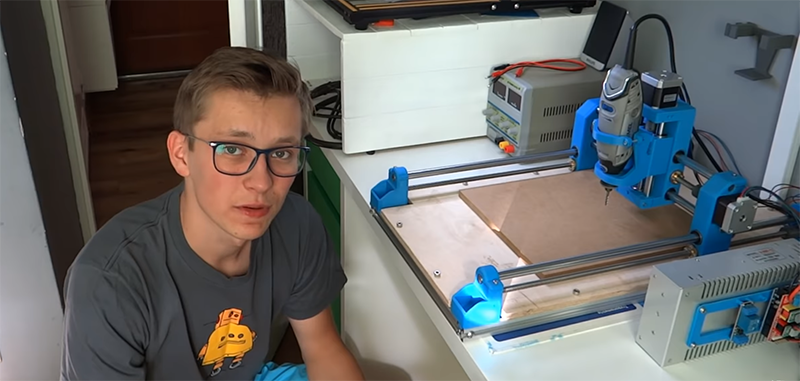

A rotary tool already spins, cuts, engraves, drills, and makes enough noise to convince the neighbors that something ambitious is happening. Mounting one on a computer-controlled motion system seems like the obvious next step. Congratulations: you have just entered the fascinating world of DIY CNC machines, where every successful engraving is preceded by several hours of measuring, wiring, calibrating, and asking why the X-axis is traveling backward.
Technically, you are not turning the rotary tool itself into a CNC. The tool becomes the spindlethe motor that rotates the cutting bit. The CNC part comes from the rigid frame, linear motion components, stepper motors, controller, software, and carefully generated G-code surrounding it.
A well-built rotary tool CNC can engrave wood, carve signs, cut thin sheet material, mill wax, shape certain plastics, and produce detailed prototypes. It will not become an industrial machining center capable of chewing through steel before lunch. The secret is designing the machine around realistic expectations.
What a Rotary Tool CNC Canand CannotDo
A rotary tool CNC works best as a compact, light-duty router or engraving machine. Its strengths are high rotational speed, small-diameter cutters, low cost, and easy replacement. These qualities make it useful for:
- Engraving lettering, logos, and decorative patterns
- Carving softwood, plywood, MDF, and machinable foam
- Cutting thin sheets with multiple shallow passes
- Making small molds, templates, signs, and craft components
- Drilling accurately positioned holes
- Producing light-duty plastic or nonferrous-metal experiments when the entire machine is sufficiently rigid
The limitations are equally important. Rotary tools generally have less torque, smaller bearings, lighter-duty collets, and shorter continuous-duty expectations than purpose-built CNC spindles or trim routers. Some compact craft-oriented rotary tools are specifically not recommended by their manufacturers for routing or heavy cutting. Always check the manual for the exact model instead of assuming that every tool with a spinning nose wants a career in automated manufacturing.
Plan the CNC Before Buying Parts
Successful CNC projects begin with a performance target, not a shopping cart. Decide what you want to cut, how large the workpieces will be, and how accurate the results need to be.
Choose a Practical Working Area
A smaller CNC is easier to make rigid. An 8-by-10-inch or 12-by-18-inch cutting area may appear modest, but it is large enough for nameplates, circuit enclosures, ornaments, coasters, small signs, and prototype parts. Doubling the travel length without strengthening the rails can turn a promising machine into a flexible noodle with stepper motors.
Remember that the machine footprint will be considerably larger than its cutting area. Rails, motor mounts, end plates, cable clearance, and the rotary tool body all consume space.
Define the Material Range
For a first build, concentrate on foam, softwood, plywood, MDF, wax, and machinable plastics approved for routing. Hard materials increase cutting forces and reveal every weakness in the frame, spindle mount, bearings, and fasteners.
Do not design around steel machining. A rotary tool CNC may scratch or lightly engrave some metals under controlled conditions, but it lacks the mass, rigidity, spindle bearings, and low-speed torque of a milling machine. Calling it a miniature machining center does not grant it miniature machining-center muscles.
Essential Components for the Conversion
The rotary tool is only one part of the system. A complete three-axis CNC requires mechanical, electrical, and software components that cooperate without arguing.
Rigid Frame
The frame may be constructed from aluminum extrusion, steel, thick plywood, laminated MDF, or a combination of materials. Aluminum extrusion is adjustable and convenient, while carefully braced plywood can work surprisingly well for a small machine.
Rigidity matters more than appearance. The cutting bit pushes sideways against the material. If the gantry twists or the Z-axis flexes, the cutter moves away from its programmed path. The result may be chatter, uneven walls, oversized pockets, broken bits, or abstract art that was not requested.
Use gussets, wide bearing spacing, short unsupported spans, and solid joints. Avoid relying on a single thin plate to support the entire Z-axis and rotary tool.
Linear Motion System
Each axis needs a controlled method of movement. Common choices include:
- Linear rails with recirculating bearing blocks
- Supported round shafts and linear bearings
- V-wheels running on aluminum extrusion
- Drawer-slide systems for experimental, low-precision builds
Linear rails generally provide the best stiffness and repeatability, but they increase cost. V-wheel systems are popular in hobby CNC construction because they are relatively simple and adjustable. Drawer slides may demonstrate the concept, although ordinary slides often contain play that appears in carved edges.
Lead Screws, Ball Screws, or Belts
The stepper motors need a way to move the axes. Lead screws offer good mechanical advantage and are suitable for compact machines. Anti-backlash nuts can reduce looseness when an axis changes direction. Ball screws provide excellent efficiency and low backlash but may be excessive for a small rotary tool build.
Timing belts are fast, inexpensive, and easy to install. They work well on lightweight X and Y axes, although long belts can stretch under cutting loads. The Z-axis is usually better driven by a lead screw because it must support the spindle assembly against gravity.
Stepper Motors
Most small DIY CNC machines use stepper motors because they move in controlled increments and can be driven without position encoders. NEMA 17 motors may be adequate for very light machines. Heavier gantries often benefit from NEMA 23 motors and more capable drivers.
Bigger is not automatically better. An oversized motor connected to an undersized driver and power supply is just a heavy object that occasionally becomes warm. Match the motor current, driver capacity, supply voltage, screw pitch, and expected axis speed as a system.
Rotary Tool Mount
The spindle mount deserves more attention than a plastic zip tie and optimism. It must hold the rotary tool securely without crushing the housing, blocking cooling vents, or allowing the nose to tilt.
A split-clamp mount made from aluminum, plywood, or accurately printed engineering plastic can work. Using two separated clamps is often stiffer than one narrow ring. Position the lower clamp as close to the tool nose as the housing allows, reducing the lever arm between the cutting bit and the Z-axis bearings.
Before final assembly, install a straight bit and rotate it by hand. Check for visible wobble. Excessive runout creates larger-than-programmed cuts and shortens tool life. Clean the collet, use the correct collet size, and avoid mounting damaged cutters.
Building the Control System
Controller and CNC Shield
A common entry-level control system uses an Arduino Uno-compatible board, a CNC shield, and plug-in stepper drivers such as the A4988 or DRV8825. GRBL firmware interprets G-code and generates step-and-direction signals for the motor drivers. GRBL communicates with a computer through a USB serial connection, making the arrangement accessible for hobby CNC projects.
Install driver modules in the correct orientation. Reversing a driver can destroy it immediately. Set the driver current limit according to the motor and driver documentation before running extended jobs. Excessive current causes overheating, while insufficient current causes skipped steps.
Add ventilation around the controller enclosure. Stepper drivers frequently need heat sinks and airflow, especially when operating near their practical current limits.
Power Supply
Select a regulated DC power supply compatible with the controller, drivers, and stepper motors. Many hobby systems operate within the 12- to 24-volt range, but the correct value depends on the electronics selected.
Do not power the rotary tool from a stepper-motor output. A corded rotary tool normally retains its own power circuit. Beginners can operate it manually with its original speed control and a properly rated external switch. Automated spindle control may be added later using suitable isolated hardware, but mains-voltage wiring should not be improvised inside an open electronics box.
Limit Switches and Emergency Stop
Homing switches give the controller a repeatable machine reference. Work zero is different: it tells the software where the programmed part begins on the actual stock. Understanding that distinction prevents a remarkable number of attempts to carve projects outside the table.
Install an accessible emergency-stop control that can remove motion and spindle power. It should be reachable without leaning across the machine. A normal software stop is useful; a physical emergency stop is useful when the computer freezes while the cutter attempts to escape.
Software: From Drawing to Motion
The basic CNC workflow consists of four stages:
- CAD: Create the drawing or three-dimensional model.
- CAM: Choose cutting tools, depths, toolpaths, feeds, and spindle settings.
- Post-processing: Convert the toolpaths into controller-compatible G-code.
- G-code sending: Transfer the program to the CNC controller while monitoring the job.
Programs such as Easel combine design, CAM, and machine control in one environment. Other workflows may use separate CAD software, CAM software, and a GRBL sender such as Candle, Universal Gcode Sender, or OpenBuilds CONTROL.
GRBL includes a check mode that parses a program without moving the axes or powering the spindle. Using a simulation or dry-run feature is a sensible way to catch unsupported commands and obvious travel errors before the cutter meets the material.
Assembling and Aligning the Machine
Square the Base and Gantry
Build the machine on a flat surface. Measure the base diagonally; matching diagonals indicate that the frame is square. Tighten fasteners gradually while checking alignment. A frame can shift as bolts are tightened, especially when assembled from extrusion.
Make sure the gantry is perpendicular to the Y-axis rails. If two motors drive opposite sides of the gantry, align both sides before connecting them mechanically or electronically.
Install the Z-Axis Close to the Gantry
Keep the rotary tool close to the gantry and avoid unnecessary Z-axis extension. Every extra inch increases leverage and reduces stiffness. Design enough vertical clearance for the intended material and fixtures, but do not build a skyscraper merely because the lead screw was available in a long version.
Route Cables Correctly
Use flexible cable, strain relief, and drag chains where practical. Keep signal wiring away from the rotary tool’s power cord. Secure cables so they cannot snag on clamps, rails, or the moving gantry.
Calibrating the Rotary Tool CNC
Set Steps Per Millimeter
The controller must know how many motor steps produce one unit of axis movement. The theoretical value depends on motor steps per revolution, microstepping, belt-pulley geometry, or lead-screw pitch.
After entering an initial value, command an axis to travel a measured distance. If the actual movement differs, calculate a corrected setting:
New steps per millimeter = Current steps per millimeter × Commanded distance ÷ Actual distance
Calibrate one axis at a time over the longest distance that can be measured accurately. GRBL and LinuxCNC configurations also include maximum travel, speed, acceleration, and limit-switch settings that must match the physical machine.
Check Backlash
Move an axis in one direction, reverse it, and observe how much motor movement occurs before the axis physically responds. Backlash may come from loose couplers, lead-screw nuts, bearings, belts, or structural flex.
Tightening everything until it becomes difficult to move is not calibration. Adjust components until play is minimized while motion remains smooth.
Tram the Rotary Tool
Tramming means aligning the spindle so that it is perpendicular to the spoilboard. A tilted tool creates ridges during surfacing and uneven pocket depths. Place a bent indicator arm or simple tramming bar in the collet, sweep it across the table, and adjust the spindle mount until both sides read consistently.
Once the machine is aligned, surface the spoilboard with a shallow toolpath. This creates a working plane parallel to the machine’s actual X and Y motion.
Feeds, Speeds, and Cutting Strategy
Rotary tools spin quickly but usually produce limited torque. That combination favors small cutters, shallow passes, and controlled feed rates.
Chip load can be estimated using this relationship:
Chip load = Feed rate ÷ (Spindle RPM × Number of cutting edges)
Manufacturer charts provide starting values, but they assume specific tooling, machines, materials, and spindle capabilities. A lightweight DIY frame may require more conservative settings.
Start Conservatively
- Use a small, sharp cutter suited to the material.
- Begin with a shallow depth per pass.
- Avoid plunging faster than the Z-axis can handle.
- Secure the stock with clamps, screws, tape-and-adhesive methods, or a fixture.
- Run the toolpath above the material before making the first cut.
- Stay beside the machine throughout the job.
Do not interpret “conservative” as “move as slowly as possible.” Feeding too slowly at high RPM may rub rather than cut, generating heat and scorching wood or melting plastic. Adjust one variable at a time and inspect the chips, sound, surface finish, and spindle temperature.
Your First Test Project
Start with a simple engraved square and circle in machinable foam or scrap softwood. This test reveals whether the machine is square, whether the axes move in the correct directions, and whether circles actually look circular.
Next, cut a shallow pocket with known dimensions. Measure it with calipers. An undersized or oversized pocket may indicate tool-diameter error, runout, backlash, incorrect calibration, or frame flex.
Only after these tests should you attempt a full-depth profile. Add tabs to keep the part from moving when the final pass separates it from the surrounding material. A loose part can become a wooden hockey puck traveling at rotary-tool speed.
Safety Is Part of the Build
A homemade CNC is still powered machinery. Rotating tools can catch clothing or hair, cutting bits can break, workpieces can shift, and chips can be thrown beyond the table. OSHA identifies rotating motion, flying chips, tool projection, electrical hazards, noise, and dust as significant woodworking risks.
Use safety glasses, appropriate hearing protection, secure workholding, guarded electronics, and effective dust collection. Keep hands away from the cutting area while the spindle is energized. Disconnect power before changing a bit, adjusting the spindle mount, or clearing a jam.
Local dust extraction positioned near the cutter is more effective than waiting for airborne dust to wander toward a shop vacuum several feet away. Research on automated routers and guidance from OSHA, NIOSH, and CNC manufacturers emphasize source collection and properly positioned exhaust equipment.
An enclosure can reduce flying debris and noise, but it should not trap heat around the rotary tool or electronics. Never leave the machine unattended simply because the lid is closed.
Common Problems and Practical Fixes
The Machine Loses Position
Reduce acceleration and feed rate, check driver current, inspect couplers, and look for binding. Skipped steps do not announce themselves politely; the machine simply continues from the wrong imaginary location.
The Cut Is Rough or Chattering
Check spindle runout, bit sharpness, mount rigidity, gantry flex, and depth per pass. Shorten the amount of cutter extending from the collet. Excessive tool stick-out increases leverage and vibration.
Circles Are Oval
Calibrate both horizontal axes, inspect belt tension or lead-screw couplers, and verify that the frame is square. Unequal axis scaling turns circles into eggs, which is useful only when the project is specifically egg-related.
The Rotary Tool Becomes Hot
Confirm that the cooling vents are unobstructed. Reduce cutting load and allow cooling periods according to the manufacturer’s guidance. Heat may indicate excessive depth, a dull bit, poor chip evacuation, or operation beyond the tool’s duty expectations.
Is the Conversion Worth Doing?
Turning a rotary tool into the spindle of a CNC machine is worthwhile when the goal is learning, engraving, craft production, or light prototype work. It teaches mechanical alignment, motion control, electronics, G-code, CAM, workholding, and machining strategy in one wonderfully complicated project.
It is less attractive when the main goal is immediate production, deep hardwood cutting, large sheet processing, or frequent aluminum machining. In those cases, a proven CNC platform with a purpose-built spindle or router may save considerable development time.
The best approach is to construct the machine so that the rotary tool can eventually be replaced. A removable spindle plate lets you begin with equipment already in the workshop and upgrade later without rebuilding the entire Z-axis.
Workshop Experience: Lessons From a Rotary Tool CNC Build
The first lesson from building a rotary tool CNC is that the spindle is rarely the biggest problem. It is the most visible component, so it receives plenty of attention, but accuracy comes primarily from the structure surrounding it. A rotary tool mounted on a rigid, square machine can produce respectable detail. The same tool mounted on a flexible gantry creates grooves that wander like a shopping cart with one damaged wheel.
During an early test, it is tempting to judge success by whether all three axes move. Motion feels exciting. The stepper motors hum, the carriage travels, and the project suddenly resembles a real machine. Unfortunately, movement alone says little about accuracy. One loose motor coupler can allow the axis to move correctly in one direction and hesitate after every reversal. The G-code remains confident while the hardware quietly develops its own interpretation.
The most useful habit is changing one variable at a time. When a cut looks bad, beginners often alter spindle speed, feed rate, depth, acceleration, and cutter type simultaneously. The next test may improve, but nobody knows why. Keeping a notebook with the bit, material, RPM setting, feed rate, depth per pass, and observed result turns random experimentation into a practical cutting database.
Workholding also becomes more important than expected. A project can survive imperfect calibration, but it cannot survive the stock moving halfway through the final pass. Low-profile clamps must remain outside the programmed toolpath. Screws should be placed where the cutter will not find them. A spoilboard is meant to be sacrificed, so cutting slightly into it is less dramatic than trying to set the work zero with microscopic perfection.
Another lesson is that sound is useful information. A smooth cut produces a relatively steady tone. Chatter, squealing, knocking, or sudden changes in pitch suggest that something has changed. The cutter may be rubbing, the stock may be loose, or the machine may be entering a direction where the gantry is less rigid. Learning to pause before the problem becomes visible can save a bit and a workpiece.
Dust control should be added during construction, not after the first MDF project turns the workshop into a powdered-furniture exhibit. A small brush skirt around the spindle and a hose supported independently from the Z-axis can improve collection without pulling on the carriage. The hose needs enough flexibility for full travel but should not be allowed to drag across the rails.
The final experience is accepting that a DIY CNC is never completely finished. After the machine makes its first successful part, the upgrade list appears immediately: better limit switches, stiffer brackets, quieter drivers, improved cable chains, a touch probe, a stronger spindle mount, and perhaps a larger machine to build parts for the smaller machine. This is normal. The real achievement is not producing a perfect CNC on the first attempt. It is building a controllable platform, measuring its weaknesses, and improving it deliberately instead of attacking every problem with another random bracket.
Conclusion
Turning a rotary tool into a CNC begins by treating the tool as one component of a complete machine. A rigid frame, accurate linear motion, properly matched motors and drivers, reliable control electronics, careful calibration, safe workholding, and realistic cutting parameters matter more than raw spindle speed.
Build small, test methodically, and begin with forgiving materials. Once the machine can repeatedly engrave, pocket, and profile simple shapes, more ambitious projects become possible. The rotary tool may be modest, but surrounded by a carefully constructed CNC system, it can become an impressively capable workshop assistantone that follows instructions literally, including the bad ones.
Note: This article is educational and does not replace the rotary-tool, controller, motor-driver, or cutting-tool manufacturers’ instructions. A DIY CNC should be operated only with suitable guarding, ventilation, electrical protection, emergency controls, personal protective equipment, and direct supervision.
Research note: This guide synthesizes technical information from Dremel, the GRBL project, Arduino resources, LinuxCNC documentation, OpenBuilds, Inventables and Easel support, Carbide 3D, ShopBot Tools, OSHA, NIOSH and CDC materials, All3DP, and HowToMechatronics.


