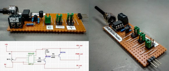

Small tools often become workshop heroes. They do not arrive with dramatic music, anodized aluminum cases, or a price tag that makes your multimeter blush. Sometimes they are just an ATtiny microcontroller, a potentiometer, a few resistors, a button, an LED, and enough clever code to make a servo twitch on command. That is exactly why an ATtiny PWM generator and servo tester is such a satisfying project: it is tiny, cheap, practical, and just nerdy enough to make you feel like you have personally negotiated peace between software and electricity.
At its heart, this project creates a controlled pulse-width signal. That signal can test RC servos, drive hobby electronics, check wiring, verify endpoints, and help diagnose the classic maker mystery: “Is the servo broken, is the code wrong, or did I plug the brown wire into optimism?” Instead of dragging out a full Arduino board every time you want to test a servo, the ATtiny25, ATtiny45, or ATtiny85 can do the job in a dedicated pocket-sized circuit.
The result is a compact PWM generator that can produce adjustable pulses and behave like a simple servo tester. Turn a knob, press a button, sweep automatically, center the servo, or use the output as a repeatable signal source while debugging a larger robotics, RC, model railway, animatronics, or automation project.
What Is an ATtiny PWM Generator and Servo Tester?
An ATtiny PWM generator is a small circuit that uses an AVR microcontroller to create pulse-width modulated signals. A servo tester is a more specific version of that idea. It outputs the kind of control pulses expected by common hobby servos: usually a pulse somewhere around 1,000 microseconds to 2,000 microseconds, repeated roughly every 20 milliseconds.
That timing matters. Many beginners hear “PWM” and imagine the same signal used to dim LEDs or control DC motor speed. Servo control is related, but not identical in practical use. With an LED, duty cycle usually determines brightness. With a hobby servo, the pulse width tells the internal control board what position to hold. A pulse near 1,500 microseconds is commonly center. Shorter pulses move one way. Longer pulses move the other way. The exact angle is not universal, because servos are tiny mechanical creatures with opinions.
This is why a dedicated tester is useful. It lets you send clean, predictable pulses without depending on a larger project. If the servo behaves correctly on the tester, the problem is probably elsewhere. If it jitters, stalls, overheats, or refuses to move, you have learned something before burying it inside a robot arm with fourteen screws and your remaining patience.
Why Use an ATtiny Instead of a Full Arduino?
The ATtiny family is popular because it gives you just enough microcontroller for small embedded jobs. The ATtiny85, for example, is an 8-bit AVR chip with flash memory, SRAM, EEPROM, timers, analog input, and several general-purpose I/O pins in a compact 8-pin package. It is not trying to be a laptop. It is trying to do one job well while taking up about as much space as a suspiciously talented black ant.
For a servo tester, that is ideal. You need one analog input for a potentiometer, one output for the servo signal, maybe a button for mode selection, and perhaps an LED to show status. A full development board can do this, but it is overkill if the goal is a permanent handheld tool.
Key advantages of the ATtiny approach
Low cost: The ATtiny25, ATtiny45, and ATtiny85 are inexpensive compared with full boards. That makes them perfect for tools you may build, lose, rebuild, and later find inside a box labeled “miscellaneous cables.”
Small size: The chip can fit into a tiny enclosure with a knob, output pins, and a power connector. A servo tester should be portable, not the size of a sandwich press.
Enough peripherals: Timers can generate accurate pulse timing, while the ADC can read a potentiometer for manual control. You get the essential pieces without dragging along unused hardware.
Good learning value: This project teaches pulse timing, timer configuration, analog reading, power layout, signal grounding, and servo behavior. It is a small circuit with a big syllabus.
Understanding the Servo Signal
A standard hobby servo usually expects a repeating control frame. The frame is often around 20 milliseconds, which corresponds to about 50 Hz. Inside that frame, the high pulse is the command. A 1,000 microsecond pulse may point the servo toward one endpoint, a 1,500 microsecond pulse usually centers it, and a 2,000 microsecond pulse moves it toward the opposite endpoint.
There are exceptions. Some servos accept wider ranges such as 500 to 2,500 microseconds. Some digital servos tolerate faster update rates. Some cheap micro servos behave like they were assembled during a thunderstorm. A good tester should therefore avoid forcing extreme endpoints by default. A safe design starts with conservative values and lets the user calibrate gradually.
Typical servo pulse examples
For practical testing, a simple ATtiny servo tester might use these pulse targets:
- Minimum: about 1,000 µs
- Center: about 1,500 µs
- Maximum: about 2,000 µs
- Frame period: about 20 ms
The servo tester does not need to know the real angle. It only needs to generate stable pulse widths. The servo translates those pulses into motion according to its own internal electronics and mechanical range. This is also why calling a command “90 degrees” can be slightly misleading. A 1,500 microsecond signal may center many servos, but the exact shaft angle depends on the model, gear train, feedback potentiometer, and factory calibration.
Basic Circuit Design
A practical ATtiny PWM generator and servo tester is refreshingly simple. The main components are an ATtiny25, ATtiny45, or ATtiny85; a potentiometer; a push button; an LED; a few resistors; a decoupling capacitor; and a three-pin servo output header. The servo header normally provides signal, power, and ground. The most important rule is that the ATtiny ground and servo ground must be connected together. Without a common ground, the signal has no reliable reference, and the servo will act like it is receiving instructions from a haunted radio.
Suggested parts list
- ATtiny85, ATtiny45, or ATtiny25 microcontroller
- 10 kΩ potentiometer for manual pulse adjustment
- Momentary push button for mode selection
- LED with current-limiting resistor
- 100 nF ceramic capacitor near the ATtiny power pins
- Three-pin male header for servo output
- 5 V regulated supply or suitable battery-powered BEC
- Optional enclosure, knob, labels, and power switch
Power deserves special attention. A microcontroller can run on very little current, but a servo cannot. Even a small SG90-style servo can draw quick current spikes when moving or holding against load. Larger servos may need far more current than a tiny regulator can provide. The tester should use a supply that matches the servo’s voltage rating and can deliver enough current. The ATtiny output pin sends only the control signal; it should not power the servo directly.
How the ATtiny Generates PWM
The ATtiny can generate timing signals in two broad ways: hardware timer output or software-controlled pulses. Hardware timers are elegant because they keep counting while the code does other things. Software timing is often easier to understand and can be accurate enough for one servo if written carefully.
For a simple servo tester, the code can read the potentiometer, map the ADC value to a pulse width, raise the output pin, wait for the selected number of microseconds, lower the pin, and then wait for the rest of the 20 millisecond frame. That is the kitchen-table version. It works, it is readable, and it is friendly to beginners.
A more advanced version uses timer registers. That approach improves consistency and reduces jitter, especially when adding button handling, LED blinking, sweep modes, or multiple outputs. The ATtiny85 includes 8-bit timers, so precision requires careful prescaler choices and sometimes creative math. A 16-bit timer would provide more room, but the whole charm of ATtiny projects is politely doing a lot with very little.
Manual, center, and sweep modes
A well-designed servo tester usually offers more than one behavior. Manual mode maps the potentiometer position to pulse width. Center mode sends a fixed 1,500 microsecond pulse, which is excellent for installing servo horns. Sweep mode automatically moves between endpoints, helping you check range, binding, and smoothness. A pulse generator mode may allow wider frequency or duty settings for non-servo experiments, such as testing LED dimmers or input capture routines on another board.
Using a push button for mode selection keeps the hardware minimal. A short press might change modes. A long press might store calibration. The LED can blink once for manual mode, twice for center mode, three times for sweep mode, and so on. This is the kind of interface that feels primitive until you realize it works perfectly and costs almost nothing.
Programming Options
You can program the ATtiny through the Arduino IDE using an ISP programmer, a USBtiny-style programmer, a dedicated tiny AVR programmer, or an Arduino configured as an ISP. The familiar Arduino environment makes the project approachable, especially for builders who want the tool more than they want a three-week vacation inside the datasheet.
However, serious builders should still understand what the libraries are doing. Standard Arduino-style functions are convenient, but they may use timers internally. If you take over a timer for pulse generation, another function may stop behaving as expected. On small chips, every timer is prime real estate. There is no spare ballroom in an 8-pin microcontroller.
Example logic flow
The program structure can be simple:
- Initialize the output pin, button pin, ADC, and timer settings.
- Read the potentiometer value.
- Convert the reading into a pulse width range such as 1,000 to 2,000 µs.
- Check whether the button changes the operating mode.
- Generate the pulse at the correct interval.
- Update the LED pattern to show the active mode.
For better usability, the code should smooth the potentiometer reading. Raw ADC values can jump slightly, which may cause servo jitter. A simple moving average or small deadband can make the knob feel much more stable. This is one of those tiny software details that makes the final tool feel less like a science fair prototype and more like something you would actually keep on the bench.
Calibration and Accuracy
The ATtiny’s internal oscillator is convenient, but it is not as precise as a crystal. For many servo-testing tasks, it is good enough. But if you need very accurate pulse widths, calibrate the oscillator or use an external clock source if the specific chip and design allow it. An oscilloscope, logic analyzer, or even another microcontroller with input capture can help verify the output.
Calibration should focus on the pulse width, not just the visible servo angle. Mechanical movement can deceive you because two servos may respond differently to the same pulse. Measuring the actual signal tells you whether the tester is doing its job. Once the output is reliable, any weird behavior is likely caused by the servo, wiring, power supply, or mechanical load.
Common problems and fixes
Servo jitters: Check power first. Add a capacitor across the servo supply, smooth ADC readings, and confirm the ground connection. Also verify that the pulse width is not bouncing because of noisy potentiometer readings.
Servo does not move: Confirm signal pin orientation. Many servo connectors use brown or black for ground, red for positive voltage, and orange, yellow, or white for signal. Plugging the connector backward is a rite of passage, but it does not have to become a lifestyle.
ATtiny resets when servo moves: The servo is probably pulling down the supply voltage. Use a stronger regulator or separate servo power with common ground.
Endpoint buzzing: The servo may be pushed beyond its comfortable range. Reduce the minimum and maximum pulse settings until the buzzing stops.
Best Use Cases for the Tool
An ATtiny PWM generator and servo tester is useful in more situations than it first appears. RC hobbyists can test servos before installation. Robot builders can center horns and check linkages. Model railway builders can tune turnout servos. Animatronics creators can test jaw, eye, and arm movements. Electronics learners can visualize pulse-width control on an oscilloscope. Repair tinkerers can separate software problems from hardware problems in minutes.
The tool also shines during prototyping. When a large project fails, reducing the system to one servo and one known-good signal is a powerful debugging move. It removes layers of uncertainty. Instead of asking, “Why does my robot arm hate me?” you can ask, “Does this servo respond to 1,500 microseconds?” That is a much friendlier question.
Building Tips for a Better Finished Tester
Use a real knob on the potentiometer. Your fingers will thank you. Label the output header clearly. Add a polarity mark so you do not need to perform archaeological research every time you plug in a servo. Put the circuit in a small enclosure if it will live in a toolbox. Hot glue is not a personality flaw, but strain relief and proper mounting are better.
Place the decoupling capacitor close to the ATtiny. Keep the servo current path away from the microcontroller signal path when possible. If you add a power switch, make sure it can handle the servo current. If you plan to test larger servos, consider screw terminals or a stronger connector instead of tiny breadboard jumpers that heat up and contemplate retirement.
A second output header can be helpful, but be realistic about the ATtiny’s resources. Generating multiple clean servo signals is possible, yet timing becomes more demanding. For a first version, one excellent channel is better than three nervous ones.
Experiences and Lessons From Using an ATtiny PWM Generator and Servo Tester
The biggest practical lesson is that a servo tester becomes more useful the moment it stops being a loose breadboard experiment. On a breadboard, the circuit teaches you how the signal works. In an enclosure, it becomes a tool. That difference matters. A finished tester with a knob, a labeled servo header, and a reliable power connector gets used often. A breadboard version gets admired once, then slowly cannibalized for jumper wires.
One common experience is discovering that not all servos agree on endpoints. You may connect one servo and see smooth motion from 1,000 to 2,000 microseconds. Then you connect another and hear angry buzzing near one end. The tester did not fail; it revealed the truth. Servos are not mathematical angels. They are gearboxes, motors, feedback pots, and tiny control boards living together in a plastic apartment. Calibration ranges should be adjustable because the real world is allergic to perfect assumptions.
Another useful lesson is that power quality matters more than beginners expect. The ATtiny may be perfectly happy, while the servo pulls enough current during startup to make the supply sag. The symptom can look like bad code: jitter, twitching, resets, random behavior, or a servo that moves once and then sulks. In practice, a stronger 5 V supply, a common ground, and a decent capacitor near the servo connector solve many “mysterious” issues. Electronics troubleshooting often begins with software suspicion and ends with a capacitor saying, “I told you so.”
The potentiometer also deserves respect. A cheap or noisy pot can make the servo tremble. Adding averaging in code makes the movement smoother. Adding a deadband prevents tiny ADC changes from constantly updating the pulse width. This is especially helpful when using the tester to hold a servo at center while installing a horn. Without smoothing, the servo may twitch just enough to make mechanical alignment annoying. With smoothing, the tool feels calm and professional.
Using a button to select modes is simple, but the interface should be obvious. Blink codes are fine if you remember them. They are less fine three months later when the tester blinks twice and you wonder whether that means sweep mode, center mode, or “please replace my battery.” A tiny printed label on the enclosure can save future confusion. Good tools communicate clearly, even when they only have one LED and the emotional vocabulary of a toaster.
The most rewarding part of the project is how much confidence it gives during larger builds. Before installing a servo into a model aircraft flap, robot gripper, camera pan mount, or railway turnout, you can test motion, center position, and mechanical limits. You can adjust linkages before connecting the main controller. You can identify weak servos before they become deeply embedded regrets. That saves time, hardware, and dignity.
Finally, the ATtiny PWM generator is a reminder that small microcontrollers are still wonderfully relevant. A modern development board with Wi-Fi, Bluetooth, USB, and enough memory to host a small poetry festival is impressive. But sometimes the right answer is an 8-pin chip generating one clean pulse over and over. It is focused. It is dependable. It does not need an operating system, cloud dashboard, or firmware update during lunch. It simply turns a knob into a pulse and a pulse into motion. In the workshop, that kind of quiet competence is worth celebrating.
Conclusion
An ATtiny PWM generator and servo tester is one of those projects that looks modest but delivers real value. It teaches timer-based thinking, servo signal timing, ADC input, calibration, power management, and practical debugging. More importantly, it becomes a tool you can actually use. Whether you are building RC models, small robots, animatronics, model railway mechanisms, or experimental electronics, a dedicated servo tester can save time and reduce guesswork.
The best design is not necessarily the most complicated one. A reliable ATtiny, a stable power setup, a smooth potentiometer, a clear mode button, and carefully written pulse-generation code can outperform a messy oversized solution. Keep the pulse range conservative, label the connector, smooth the input, and give the servo enough current. Do that, and this tiny tester will earn a permanent place on your benchprobably right next to the screwdriver you keep losing.
Note: The timing values discussed here are typical for hobby servos. Always check the specifications of your servo, power supply, and microcontroller version before connecting hardware.


