
Electronics is full of rules. Use resistors to resist, capacitors to store charge, transistors to switch, and fuses to sacrifice themselves heroically when current gets too enthusiastic. Then along comes the 2025 Component Abuse Challenge, cheerfully kicking the rulebook under the bench and asking, “But what else can this part do if we squint at it creatively?”
One of the most delightfully strange answers is a bistable flip-flop with a fuse. Yes, a fuse. Not a logic IC. Not a pair of transistors. Not a relay clicking away like it has a tiny mechanical opinion. A fuse specifically a PTC self-resetting fuse used as part of a working set/reset memory circuit. It is the kind of project that makes experienced engineers blink twice, beginners lean forward, and safety-conscious people instinctively ask where the current-limited bench supply is.
The project, created by b.kainka and featured in Hackaday’s 2025 Component Abuse Challenge coverage, uses a pair of PTC fuses, two incandescent bulbs, and momentary switches to create a circuit that can settle into one of two stable states. In plain English, it remembers which bulb should be on. That is the heart of a flip-flop: a simple electronic memory element with two possible states. The twist is that this one gets there through heat, resistance, imbalance, and a bit of component mischief.
What Is the 2025 Component Abuse Challenge?
The Component Abuse Challenge is a maker contest built around one wonderfully chaotic idea: use electronic parts in ways they were not really intended to be used, while still making a functional project. This is where LEDs become light sensors, capacitors act like microphones, resistors become heaters, and fuses apparently decide they would like a career in digital logic.
That does not mean “random destruction with a soldering iron,” although the phrase certainly has a certain garage-lab poetry. The best entries are not just silly; they reveal hidden physical behavior inside ordinary parts. They show that components are not ideal textbook symbols. They are little chunks of material with temperature curves, delays, capacitance, leakage, resistance changes, and quirks. In normal engineering, those quirks are problems to minimize. In component abuse, they become the main event.
Why a Fuse Flip-Flop Is So Clever
A normal fuse is designed for protection. Too much current flows, the fuse opens, and the circuit is interrupted. A traditional one-time fuse is done at that point. It has performed its dramatic final act and must be replaced. A PTC resettable fuse, also called a polymer positive temperature coefficient fuse or polyfuse, behaves differently. When it heats up, its resistance rises sharply, limiting current. When the fault or heat source is removed and the device cools, it can return toward a lower-resistance state.
That behavior is supposed to protect circuits. In this project, it becomes the switching mechanism. Instead of asking the PTC fuse to prevent disaster, the circuit asks it to choose a side. One fuse becomes hot and high-resistance while the other remains cool and low-resistance. That difference creates a visible output: one incandescent bulb lights while the other stays dark.
In other words, the fuse is not merely reacting to the circuit. It is helping define the circuit’s state. That is the abuse, and also the genius.
Understanding the Bistable Flip-Flop
A bistable flip-flop is a circuit with two stable states. In digital electronics, this is foundational. Flip-flops and latches are used to store bits, build counters, shift data, synchronize signals, and create sequential logic. They are the tiny memory muscles of digital systems.
In a conventional set/reset latch, there are two outputs, often labeled Q and not-Q. When one output is on, the other is off. Press or pulse the set input, and the circuit moves into the set state. Trigger the reset input, and it moves into the reset state. When neither input is active, the circuit holds its previous state.
Usually, you would build this with cross-coupled NOR gates, NAND gates, transistors, or a ready-made logic IC. That is the practical way. It is neat, fast, compact, predictable, and unlikely to make an incandescent bulb part of the conversation. But the fuse-based version teaches something different. It shows that “state” does not have to come only from silicon logic gates. State can also emerge from thermal feedback and resistance changes.
How the PTC Fuse Flip-Flop Works
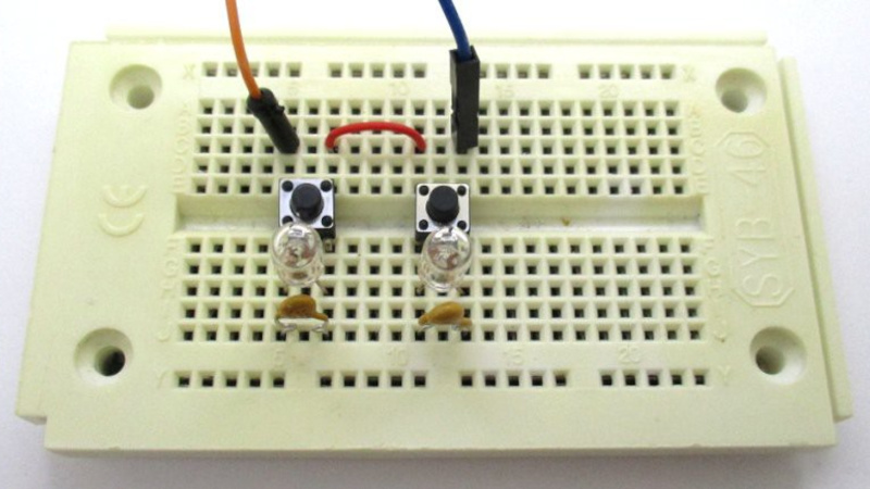
The circuit is beautifully minimal: two incandescent bulbs in series, two PTC resettable fuses, and two momentary push buttons. Each bulb has a PTC fuse and a switch arranged around it so the state can be nudged from one side to the other.
At startup, both PTC fuses begin in a relatively low-resistance condition. Current flows. Because real components are never perfectly identical, one side heats slightly differently or reaches its transition point first. That PTC fuse increases resistance. Once it goes high-resistance, its associated bulb lights while the opposite side remains low-resistance and dark. The circuit has fallen into one of two stable states.
Pressing the switch across the lit bulb changes the current and thermal balance. Hold it for a few seconds, and the system flips. The previously hot fuse cools toward a lower-resistance state, while the other PTC device heats and rises in resistance. The lit bulb goes dark, the dark bulb lights, and the flip-flop has changed state. It is not fast. It is not efficient. It will not replace a 74HC74 on your next PCB. But as a physical demonstration of bistability, it is wonderfully memorable.
The Role of Heat, Resistance, and Imperfection
The magic ingredient is temperature-dependent resistance. A PTC resettable fuse increases resistance as it heats. An incandescent bulb also has a temperature-dependent filament. When cold, the filament has a much lower resistance than it does when glowing hot. That means the circuit is full of parts whose electrical behavior changes as they warm up.
This makes the fuse flip-flop feel almost alive. It has a warm-up personality. It does not snap instantly like CMOS logic. It drifts, tips, settles, and remembers. The circuit depends on small differences between the two sides. If everything were perfectly identical, startup would be ambiguous forever. But the real world is kind enough to be imperfect. One fuse warms a little faster. One bulb behaves slightly differently. One wire has a hair more resistance. The universe provides the tie-breaker, as it so often does, without even asking for a datasheet.
Why This Counts as Component Abuse
A PTC fuse is sold as a protection device, not a memory element. Its job is to limit current during overcurrent conditions and recover after cooling. Using that trip-and-reset behavior as the basis for a flip-flop is a textbook example of component abuse: the part is doing something real and useful, but not what the manufacturer had in mind when writing the application note.
That is what makes the project so educational. The fuse is not being used randomly. Its physical behavior is understood well enough to be bent into a new function. The abuse is not ignorance; it is informed mischief. That distinction matters. Good hacking is not just “what happens if I plug this in backward?” It is “what hidden property can I exploit safely and intelligently?”
Is It Practical?
Let’s be honest: if you are designing a commercial product, a fuse-based flip-flop is probably not your best choice. It is slow, thermal, power-hungry, and dependent on component behavior that may vary with ambient temperature, part tolerance, airflow, and aging. If your refrigerator, car, or medical device uses this as mission-critical logic, someone in the design review has made a bold life choice.
But practicality is not the only measure of value. This circuit is useful because it is visible. Most digital memory is invisible unless you connect probes, LEDs, or logic analyzers. Here, the memory state is glowing right in front of you. One bulb says “set,” the other says “reset.” The PTC fuse acts like a thermal decision-maker. You can watch the circuit think slowly, like a Victorian computer enjoying a cup of tea.
What Makers Can Learn From It
1. Components Are Physical Objects, Not Just Symbols
A schematic symbol is a polite simplification. Real parts have temperature coefficients, parasitic capacitance, leakage, mechanical limits, and response times. A PTC fuse is not just a fuse symbol. It is a temperature-sensitive resistor with memory-like recovery behavior. An incandescent lamp is not just a light source. It is a non-ohmic resistor that changes dramatically as it heats.
2. Feedback Creates State
Flip-flops rely on feedback. In gate-based logic, feedback is electrical and fast. In this fuse circuit, feedback is thermal and slow. Still, the core idea is similar: one condition reinforces itself until the circuit settles into a stable state. That is a powerful lesson for anyone learning electronics.
3. “Wrong” Uses Can Teach Right Lessons
Using a fuse as a logic element is not recommended for ordinary design, but it teaches thermal behavior, hysteresis, current limiting, latch concepts, and startup race conditions in one compact experiment. That is a lot of education from a handful of parts.
Safety Notes Before You Get Too Inspired
Projects like this should be treated as educational experiments, not consumer-ready gadgets. Use low voltages, current-limited supplies, properly rated parts, and common sense. PTC fuses heat up during operation. Incandescent bulbs also get hot. Keep flammable materials away, avoid mains voltage unless you are qualified, and remember that “component abuse” is funnier when the component is the only thing being abused.
The safest version of this kind of experiment belongs on a bench with a low-voltage DC power supply, insulated connections, and enough patience to let parts cool between tests. Good hackers laugh at the weirdness, but they still respect electricity.
Why This Project Stands Out in 2025
The 2025 maker scene is overflowing with AI boards, tiny microcontrollers, wireless modules, and polished development kits. Those tools are amazing, but they can also hide the raw physics of electronics. A fuse-based bistable flip-flop does the opposite. It strips the idea of memory down to heat, resistance, and imbalance.
That is refreshing. It reminds us that digital logic did not appear from nowhere. It grew from physical devices: relays, tubes, magnetic cores, transistors, and eventually integrated circuits. The PTC fuse flip-flop belongs to that same storytelling tradition. It is not the future of computing, but it is a bright little reminder of how weird and wonderful the foundations can be.
Experience Section: What Building or Studying a Fuse Flip-Flop Teaches You
Spending time with a circuit like the 2025 Component Abuse Challenge: A Bistable Flip-Flop With A Fuse changes how you look at ordinary parts. At first, the idea sounds like a joke. A fuse stores a bit? Sure, and my toaster is a cloud server. But once you trace the behavior, the joke becomes a lesson. The PTC fuse has two useful regions: cool and low-resistance, hot and high-resistance. That is already a kind of state machine, just not one printed in a digital logic textbook.
The first experience is patience. Anyone used to modern logic expects immediate response. Push a button, get a clean transition. With a PTC fuse flip-flop, the circuit has timing you can feel. The switch press needs a moment. The fuse needs to heat. The other side needs to cool. The bulbs respond with that old-school glow that says, “Give me a second; I am made of tungsten and drama.” This slower behavior makes the circuit easier to observe and strangely more satisfying.
The second experience is respect for tolerances. In theory, both sides of the circuit may look identical. In practice, one always wins the startup race. That little imbalance is not a flaw here; it is the mechanism that allows the circuit to choose a stable state. When you see that happen, tolerances stop being boring numbers buried in datasheets. They become active characters in the story.
The third experience is learning how feedback can appear in unexpected forms. Most beginners think feedback means an output wire connected back to an input. That is true, but feedback can also be thermal. Current heats a fuse. Heat changes resistance. Resistance changes current. Current changes bulb brightness. Bulb brightness tells you which state the circuit has chosen. The loop is not only electrical; it is physical.
The fourth experience is understanding why engineers usually avoid this approach. Temperature changes slowly. Ambient conditions matter. Components age. If you blow air across one side, use mismatched bulbs, or choose fuses with different trip characteristics, behavior can shift. That is not a criticism. It is the lesson. Practical engineering often means removing uncertainty. Experimental hacking often means inviting uncertainty in, giving it coffee, and asking what tricks it knows.
The fifth experience is rediscovering curiosity. A project like this encourages a powerful question: “What else can this part do?” That question is behind many great electronics experiments. LEDs can sense light. Speakers can act as microphones. Motors can become generators. Capacitors can remember charge longer than expected. Wires can become antennas whether you invited them to or not. The fuse flip-flop belongs to that tradition of looking at a component sideways and finding a hidden personality.
For educators, this circuit is a conversation starter. It connects digital logic, thermal physics, current limiting, resistance curves, and circuit protection in one memorable demonstration. For makers, it is a reminder that not every useful project needs a microcontroller. For engineers, it is a playful warning that non-ideal behavior is always there, whether you exploit it or fight it.
Most of all, the fuse-based flip-flop captures the spirit of hardware hacking: understand the rules deeply enough to break them with style.
Conclusion
The 2025 Component Abuse Challenge: A Bistable Flip-Flop With A Fuse is more than a quirky circuit. It is a small glowing lesson in how real components behave when pushed beyond their job descriptions. By turning PTC resettable fuses into the active memory elements of a bistable circuit, the project transforms a protection device into a logic demonstration. It may not be practical in the commercial sense, but it is brilliant in the educational sense.
It shows that electronics is not only about clean schematics and perfect logic levels. It is also about heat, timing, tolerance, feedback, and the charming stubbornness of physical parts. In a world of tiny chips that hide their complexity inside black plastic packages, a fuse flip-flop proudly puts the weirdness on display. One bulb glows, the other waits, and a fuse quietly pretends it was born to remember.


